The most expensive mistake we see in Oakville is a tender package that assumes uniform shale at 3 metres. Then the excavator hits a buried valley filled with saturated till east of Sixteen Mile Creek. You’re into dewatering, redesigning footings, and losing three weeks. Seismic tomography cuts that risk before the first bucket moves. We’ve run refraction lines across the Glen Abbey and Bronte Creek corridors where bedrock can swing from 2 to 18 metres within a single lot. The method sends a hammer or weight-drop signal through the ground, and a geophone spread picks up travel times. We process those arrivals to map velocity layers: soil, weathered shale, and competent Queenston Formation rock. When the site is tight or noise from the QEW is a problem, we switch to reflection tomography for a sharper picture of deeper interfaces. MASW surveys often pair with this when the structural engineer also needs VS30 for NBCC site classification, and test pits let us ground-truth a couple of key stations without over-excavating.
Refraction velocity jumps from 600 m/s to 2400 m/s in less than half a metre — that’s your bedrock line, and we map it within 10 centimetres.
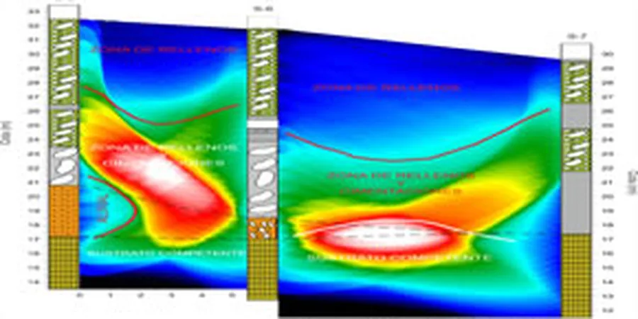
Methodology and scope
Local considerations
The kit on the truck is simple but the logistics in Oakville matter. We use a 24-channel seismograph with 4.5 Hz vertical geophones on a takeout cable. For a standard refraction spread, that’s 115 metres of cable laid straight across a building footprint or along a proposed sewer alignment. The trigger is a sledgehammer on an aluminum plate; in the winter, when the top 20 cm of clay is frozen solid near Dundas Street, we pre-drill a small pilot hole to get decent coupling. One hidden risk in the Bronte Bluffs area is a thin high-velocity caprock over soft weathered shale. A naive interpretation reads the caprock as competent bearing, but reflection mode or a single SPT borehole at the anomaly reveals the story: you’re building on a brittle lid over a compressible layer. We flag that in the report with a direct velocity-depth warning so the structural engineer doesn’t size footings on false assumptions. Another Oakville-specific challenge is cultural noise — the Lakeshore Road corridor has constant truck vibration that can swamp low-amplitude signals. We stack shots 5 to 8 times per station and run a spectral filter in the field to keep the first break picks clean.
Applicable standards
ASTM D5777-18: Standard Guide for Using the Seismic Refraction Method, NBCC 2015: Site Classification for Seismic Site Response (Table 4.1.8.4.A), ASTM D7128-18: Standard Guide for Using the Seismic Reflection Method
Associated technical services
Refraction Tomography for Building Foundations
2D velocity mapping for residential and commercial footings. We deliver a bedrock contour with rippability zones so your excavator tender is accurate. Typical line: 69-metre spread, 5-metre spacing, processed within three business days.
Reflection Surveys for Deep Infrastructure
For proposed parking garages, deep shoring, or tunnel alignments where bedrock is beyond 30 metres. We use a 48-channel array with a weight-drop source and CDP stacking to image stratigraphy that refraction won’t reach.
Combined MASW + Refraction for Site Class
NBCC site class requires VS30. We run a single geophone spread, process the refraction for P-wave velocity, then switch to surface-wave inversion for shear-wave velocity. One mobilization, two deliverables.
Typical parameters
Frequently asked questions
What does seismic tomography cost for a typical Oakville residential lot?
For a standard single-family lot in Oakville, a refraction tomography survey with one 69-metre line typically runs between CA$3.450 and CA$4.800 depending on access, line clearing, and whether we need a second spread for orthogonal coverage. Larger commercial sites requiring multiple lines or reflection processing fall in the CA$5.200 to CA$6.570 range.
Can you do this survey on a frozen site in January?
Yes, but frozen ground affects coupling. We pre-drill small pilot holes at each geophone station to get below the frost layer, and we increase the stack count to compensate for the stiffer near-surface. The velocity model still resolves bedrock accurately.
How long does the field crew need on site?
A single refraction line takes about 90 minutes to lay out, shoot, and pick first arrivals. If we’re running two or three lines, expect a half-day mobilization. Data processing and report delivery happen within three to five business days after the field work.
Do you need to drill any holes for this method?
No drilling is required for the geophysical survey itself. The method is entirely surface-based. We do recommend at least one calibration borehole or test pit on larger projects to tie the velocity model to a known lithology, which improves confidence for the geotechnical engineer.